As well as devices needing to be compliant, in some cases it will be necessary to implement them with a certain level of redundancy. The level of redundancy you must implement is dependent on the target SIL, the compliance route and (in some cases) the characteristics of the device.
(Note that the wording for HFT in IEC 61511 lacks clarity and many people misunderstand HFT requirements as a result).
The HFT is worked out device by device. It is often the case that there are different HFT requirements for the different devices in each SIF.
Hardware Fault Tolerance is, as you’d expect from the name, the ability to tolerate hardware faults. A 1oo2 (1 out of 2) redundant arrangement can tolerate 1 hardware fault, so has HFT = 1. A 2oo3 arrangement also has HFT =1. 1oo1 has HFT = 0, so there is no tolerance to hardware faults.
The HFT requirements of both Route 2 “Proven in Use” (from IEC 61508) and “Prior Use” (from IEC 61511) compliant devices are the same. This makes sense as the two routes are very similar in philosophy – using historical records to confirm likely future failure rates. The HFT can be found from the table below:
SIL |
Minimum Hardware Fault Tolerance |
1 |
0 |
2 (low demand) |
0 |
2 (continuous / high demand) |
1 |
3 |
1 |
4 |
2 |
The HFT requirements for Route 1 “By Design” compliant devices are a little more complicated. The complexity reflects the fact that Route 1 devices have typically achieved their target SIL level by careful, safe design, matched with achieving a target level of internal diagnostics. Additionally, the HFT requirements recognise that simple (typically analogue only) devices can be used with lower level of redundancy than more complex (typically digital) devices.
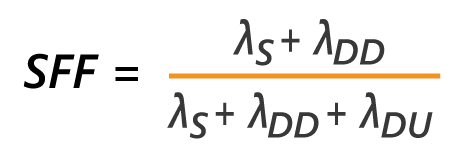
Safe Failure Fraction (SFF) at one level is as you’d expect – it describes the fraction of “all” failures that are “safe”. But there are some subtleties here. “All” failures exclude irrelevant failures and “safe” failures include dangerous diagnosed failures (which are taken as safe as you will be made aware of them and can do something about it). SFF then tells you (indirectly) what proportion of failures are dangerous undetected. The equation for SFF is as below. “Lambda” (λ) is the accepted symbol for failure rate, the suffix shows if the failure rate is Safe (S), Dangerous Detected (DD) or Dangerous Undetected (DU)
Simpler devices are known as “Type A” devices, more complex ones (such as the ones that use a microprocessor as part of the safety function of the device) are “Type B”. You’ll see that the HFT table below for Route 1 HFT is split in to two halves for each Type.
Almost all devices that have Route 1 compliance will have a data sheet / certificate that provides the data you need. The Type will be defined as A or B. The SFF will be given – or the data to calculate the SFF will be provided.
From the device’s Type and SFF, you can find the correct HFT for the target SIL. Remember that this is repeated for each device in the SIF and – since each device may have a different Type and SFF – the devices in a particular SIF may have different HFT requirements. (A sensor might need HFT of 1, logic solver HFT of 0, final element HFT of 2. Until you have the device Type and SFF you won’t know what the HFT is for each device at a particular SIL).
|
Type A |
Type B |
||||
SFF |
HFT=0 |
HFT=1 |
HFT=2 |
HFT=0 |
HFT=1 |
HFT=2 |
< 60% |
SIL 1 |
SIL 2 |
SIL 3 |
N.A. |
SIL 1 |
SIL 2 |
60% - < 90% |
SIL 2 |
SIL 3 |
SIL 4 |
SIL 1 |
SIL 2 |
SIL 3 |
90% - < 99% |
SIL 3 |
SIL 4 |
SIL 4 |
SIL 2 |
SIL 3 |
SIL 4 |
> 99% |
SIL 3 |
SIL 4 |
SIL 4 |
SIL 3 |
SIL 4 |
SIL 4 |
Project is to determine whether the Probability of Failure on Demand (PFD) for an installed SIS meets the target PFD of 0.1 presented in the LOPA review. The PFD calculated for the SIF was then incorporated into an update to the LOPA.
Industry: Mining / Metal / CementFollowing several inspections by the UK Competent Authority (HSE), a project to deliver an alarm review process for several UK sites. The project comprised: Phase 1 – Undertake an Alarm Review. The outputs being a provisional master alarm database, a draft alarm response manual and a proposed action list, (these documents to be finalised in phase 2). Phase 2 – Actions Close Out and Update. Phase 1 generated several actions to be resolved, by the software owner (how alarms actually activate, what executive actions they have). Phase 2 also updated the master alarm database and alarm response manual. Phase 3 – KPI Introduction. Began measuring the KPIs required and instigated regular alarm review sessions for the site, as defined by the Alarm Handling Policy, Phase 4 – Introduction of Alarm updates. Defined and began the process, set priority levels, deleted unneeded alarms and implemented wider changes to bring the BPCS in line with the new policy.
Industry: Brewing and DistillingProject to carry out a Safety Instrumented Function (SIF) Safety Integrity Level (SIL) and Probability of Failure on Demand (PFD) Calculation Verification on four SIFs.
Industry: Mining / Metal / CementProject to investigate client's approach to HAZOP, LOPA and PFD Calculation where multiple SIFs protect a single hazard. Confirm whether approach CCF used is in line with current best practice.
Industry: ChemicalProject to carry out SIL Verification and confirmation of PFD calculations for x22 SIF's.
Industry: Oil and Gas OnshoreE: support@methodfs.com. T: 44 (0)1462 713313. W: www.methodfs.com


 Keep up-to-date